ATR Enclosures: Rugged Protection for Military Systems

Experience shows up in places an ATR enclosure datasheet never captures. Suppliers who've spent years designing around SOSA aligned systems and decades around OpenVPX, and the wider VITA and Eurocard architectures have already made the mistakes your program can't afford to repeat. They know which decisions ARINC 404A leaves open, and where those decisions go wrong. Pick a supplier without that history, and the risk transfers to your program.
Standard ARINC 404A dimensions guarantee the chassis mounts in the tray. They don't guarantee thermal performance matches your heat dissipation, that your backplane supports the card profiles you selected, that I/O panel apertures align with platform connectors, or that power supply voltage rails match what your boards need.
The difference between success and failure comes down to asking the right questions before procurement.
What cooling interface does your mounting structure provide? Do your cards match the backplane's SOSA profile? Will the backplane perform at the specified levels? Will the best I/O connectors be chosen that optimize the system capabilities within the enclosure's physical constraints and access requirements? Will the chassis cool the plug-in cards properly to the system's environmental requirements?
Programs that skip these questions during selection end up answering them during integration issues or, worse, qualification failures, when fixes cost more and take longer.
Picking the Right ATR Size for Your Application
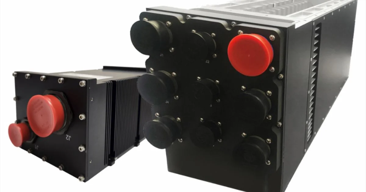
ARINC 404A defines standard widths: 1/4 ATR, 1/2 ATR, 3/4 ATR, and full ATR, but it's not uncommon to find sizes in between. This is especially true when airflow (or liquid) is introduced into the sidewalls of the enclosure. Standardization allows qualified designs to be adapted across platforms; a chassis qualified for one aircraft can support a different platform with I/O panel modifications rather than complete redesign.
Your backplane architecture interacts with form factor selection. OpenVPX backplanes supporting high-speed serial protocols have different spacing requirements than legacy parallel bus architectures. Many VME systems sat at 0.8" pitch, while OpenVPX is typically at 1".
Different cooling approaches move the pitch too. Air Flow Through (AFT) designs under VITA 48.5 and 48.8 push cooling air through a sealed heat frame inside the module, keeping electronics away from ambient air.
That heat frame takes space; VITA 48.8 modules typically sit at 1.2" or 1.5" pitch rather than 1". Liquid Flow Through (LFT) under VITA 48.4 routes coolant through an integral heat sink instead and handles the highest per-slot heat loads.
SpaceVPX, VNX+, and the upcoming VITA 100 architecture all bring different slot pitch options as well. The VITA organization defines the standards that govern these architectures.
MIL-STD Compliance Beyond the Datasheet
MIL-STD-810 covers shock and vibration testing across multiple environmental conditions. MIL-STD-461E covers electromagnetic compatibility and emissions limits. Your chassis supplier's spec sheet might claim compliance for the empty chassis, but that compliance doesn't automatically transfer to your integrated system once you've loaded boards, installed cable assemblies, and mounted the configuration in your platform.
A chassis tested empty doesn't represent your actual configuration. Board mass changes vibration response and natural frequencies. Thermal loads shift temperature distributions. Cable routing creates electromagnetic coupling paths absent in the baseline test configuration.
Thermal testing under load catches mismatches between predicted and actual heat rejection. Boards running thermal management algorithms can boost power beyond nominal ratings during processing peaks when all cores activate during demanding workloads.
Choosing an advanced cooling method is usually application-dependent. Some applications don’t have adequate airflow available to cool a chassis, so conduction-cooled-or liquid-cooled options are more prevalent. Convection-cooled designs need conditioned airflow, while conduction-cooled configurations depend on mounting interface thermal characteristics.
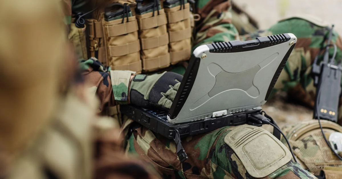
Rugged embedded systems in ATR form factors face different environmental stresses by platform type. Airborne systems see rapid temperature cycling during altitude changes and sustained vibration from engine or rotor sources. Ground vehicles deal with shock loads from rough terrain and dust infiltration. Naval platforms add salt spray exposure and high humidity that accelerate corrosion if sealing isn't adequate.
Utilizing backplane/chassis vendors with experience in multiple environments, cooling platforms, and design approaches provides the user with the best defense against unexpected issues arising.
SOSA-Aligned Backplanes and Interoperability
.webp)
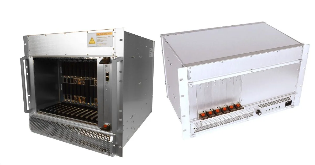
SOSA-aligned backplanes narrow down dozens of possible OpenVPX configurations to specific plug-in card profiles defined by the SOSA Consortium. Instead of a near endless array of possible backplane customization configurations for every program, you're working from standardized 3U and 6U profiles.
This matters for 3U SOSA aligned ATR configurations because it increases the probability cards from different vendors will work together. Backplane slot profiles, connector pinouts, and power distribution follow SOSA Technical Standard guidelines.
SOSA alignment doesn't guarantee plug-and-play interoperability. There are still a huge number of design possibilities even with a limited number of SOSA slot profiles. So, performing backplane signal integrity simulation for particularly the highest speeds, is worthwhile.
Although additional SI work and testing is merited, staring from the baseline of a standard architecture helps to significantly reduce risk and improve integration time.
When Standard Configurations Need Adaptation
An ATR enclosure's external dimensions will often stay fixed, the internal configurations adapt to match mission requirements.
Backplane slot counts adjust to match payload requirements. I/O panels can be customized to match your connector types: VITA 67 RF connectors, VITA 66 optical apertures, or MIL-DTL-38999 circular connectors.
Power supply options (AC or DC, voltage rails, capacity) affect what fits alongside payload cards. High-capacity power supplies consume space. Module width variations can also affect the chassis design. So, there are a significant amount of configuration options, even in standardized architectures.
Questions That Expose Problems Early
What cooling interface does your platform require? Depending on the cooling option (conduction, airflow over conductive fins, AFT, LFT, etc.) there are design considerations for each approach. Thermal simulation is a helpful tool to provide guidelines for proper thermal management.
How are you loading cards: front, rear, or top? This affects chassis orientation, I/O panel locations, and whether your platform access allows the required configuration.
What's your backplane architecture and speed requirement? Different architectures have different connector densities and signaling capabilities. OpenVPX backplanes supporting PCIe Gen3 or Gen4, 40GbE, or 100GbE have specific requirements that affect chassis design. VITA 91 provides even higher speed options. In the future, VITA 100 designs will bring new speeds, along with new challenges.
Do your plug-in cards match your backplane's SOSA profile? Verify SOSA and VITA profile compatibility and expansion plane pinouts before assuming cards will work with a SOSA-aligned backplane. Profile mismatches show up during integration when they're expensive to fix.
What MIL-STD qualification testing will your integrated system undergo? If you need MIL-STD-810 qualification for the complete assembly, verify the chassis supplier can provide test data for similar configurations. Starting with a previously qualified chassis platform reduces qualification risk.
What Supplier Experience Buys Your Program
Design failures trace back to a decision made without having seen the problem before. Suppliers who've designed MIL rugged VITA and Eurocard-based systems have already hit these thermal, mechanical, and profile mismatches on other programs. They recognize the warning signs in your requirements before metal gets cut.
That pattern recognition is what you're buying with an experienced chassis supplier. The ATR enclosure itself is the easy part.
Questions about ATR configurations for your platform? Contact our engineering team to talk through cooling, backplane, and qualification requirements before they turn into schedule risk.