Choosing an Advanced Cooling Method for Your Embedded System

Rugged embedded systems used in military and aerospace applications are pushing traditional cooling methodologies past their thermal limits. Learn the differences between conduction, AFT, AFB, and LFT, and the right questions to ask when choosing an advanced cooling method for your embedded system.
In rugged applications, embedded systems are often housed in sealed, air-tight enclosures (ATRs) to protect them from the harsh environment around them.
This necessary ruggedization creates a thermal management challenge: the enclosure that protects the components also traps 100% of their waste heat. This problem is only intensifying as the power-hungry CPUs and GPUs behind Signals Intelligence (SIGINT), Electronic Warfare (EW), and Artificial Intelligence (AI) and other advanced applications are packed into compact 3U and 6U VPX form factors aligned with the Modular Open Systems Approach (MOSA).
Poor thermal management can cause system failures and significantly shorten the life of components. For every 18°F (10°C) increase in temperature, the Mean Time Between Failure (MTBF) decreases by approximately 50%.
Solving this thermal challenge requires moving beyond traditional cooling to more advanced methods. However, because wattage levels and applications vary so widely, there is no singular advanced cooling solution. It’s a balancing act between power requirements, physical space, the level of ruggedization, and thermal performance.
Here, we’ll walk you through the limits of traditional thermal management for embedded systems and then move on to the advanced cooling methods required for today's high-wattage MOSA and SOSA®-aligned embedded systems.
Why Some Traditional Cooling Methods May Not Be Enough
Conduction cooling has historically served as the primary rugged solution. It's a fanless process that uses the enclosure itself as a passive heat sink. Heat is pulled from the module into the chassis sidewalls via a conduction plate and wedge locks. Its high reliability (no moving parts) makes it ideal for high-vibration environments.
However, conduction cooling has inherent limitations. OpenVPX is the de-facto standard for MOSA and SOSA based military/aerospace systems.
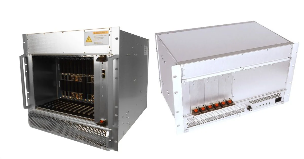
Forced-air convection cooling, conversely, uses fans to blow air directly across the electronics. For benign environment OpenVPX systems, Pixus has developed an efficient approach with airflow directly above the cards. These powerful hot-swappable blowers are 191 CFM each, pulling air up from the cards (one axis) and exhausting the heat 90 degrees out the back of the system. The fans can be speed controlled either manually with a potentiometer or via thermistors or a fan controller. The PixCool chassis allows for the use of Rear Transition Modules (RTMs) without adding to the chassis's rack height.
This design is also far more efficient (70% efficiency vs. 20% for typical muffin fans) and provides at least 70-75% higher airflow than a typical 19" rackmount fan tray under the same high-impedance conditions.
While it can handle extremely high thermal loads, it cannot be used for rugged applications where it requires a sealed system that must be protected from dust and moisture.
For more rugged applications, the design requires MIL grade fans that can survive the elements, as well as shock, vibration, and meet EMI considerations. In these systems, the airflow does not typically go over the cards themselves, but over internal fins in the enclosure which dissipate the heat from the plug-in card’s conduction-cooled design. In OpenVPX systems, these designs are per VITA 48.2 The airflow from the fans cool the fins so that more heat can be dispersed. This applies in both rugged rackmount and ATR (Air Transport Rack) style of OpenVPX systems.
Advanced Cooling Methods for Rugged Embedded Systems
When traditional methods fall short, designers turn to a portfolio of advanced cooling and hybrid thermal management for embedded systems. While these standards provide the necessary blueprint for interoperability, the physical reality of cooling high-power silicon requires specialized engineering beyond the spec.
1. Hybrid Cooling: Air Flow Through (AFT) & Air Flow By (AFB)
Air Flow Through (AFT) and Air Flow By (AFB) are hybrid cooling methods that combine forced-air cooling with conduction cooling to cool high-power components while protecting them from dust and moisture.
Instead of blowing air onto the electronics, AFT (ANSI/VITA 48.8 or designs such as VITA 48.5), directs air through an internal, isolated heat exchanger built right into the module.
Each module features its own sealed thermal path, complete with an inlet and an exhaust, enabling the module to remain fully sealed from the environment. And because it doesn't rely on a conduction wedge lock, AFT modules can use lightweight jack screws, often providing a SWaP benefit by replacing the heavy retainers used in VITA 48.2.
A related method is AFB (ANSI/VITA 48.7). AFB directs cooling air around the outside of a sealed chassis to pull heat away from its external surfaces. Like AFT, the cooling air never encounters the electronic components or connectors.
Pixus has developed a test/development chassis that supports VITA 48.5/VITA 48.9/48.8 AFT boards as well as VITA 48.1 (direct air-cooled) and VITA 48.2 conduction-cooled cards.
2. Liquid Cooling
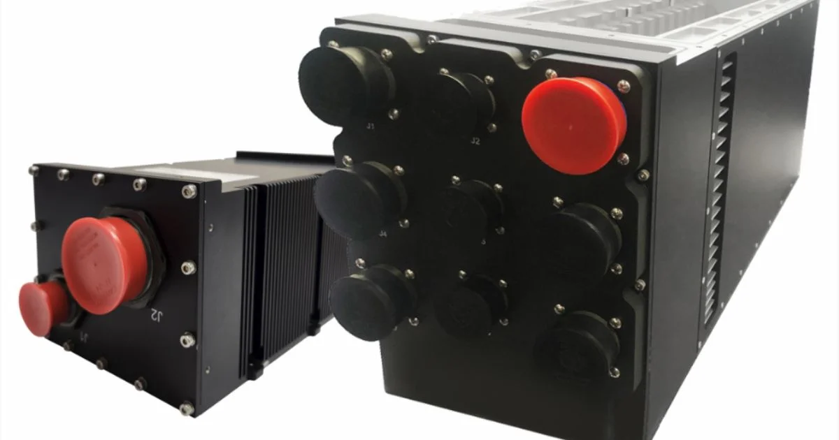
When even advanced air-based methods can't handle the heat, designers often turn to liquid cooling. The most direct implementation is Liquid Flow Through Cooling (LFT) (ANSI/VITA 48.4). This method flows a coolant (such as PAO (Polyalphaolefin), seawater, kerosene, or other coolants) directly through an integral heatsink built into the module itself. Using quick-disconnect couplings, the plug-in module fluidically couples to the chassis's coolant manifold, creating a highly efficient, self-contained loop.
A common alternative is using liquid cooling through sidewalls. This approach actively circulates liquid through the chassis walls, effectively pulling heat away from the card edges more aggressively than passive conduction. It comes with the significant benefit of being able to plug in standard VITA 48.2 cards, which are far more common, lower cost, and less complex. Pixus offers rugged ATR versions utilizing liquid-cooled sidewalls or VITA 48.4 designs.
Liquid is much more efficient at carrying and transferring heat than air. Depending on the fluid (e.g., water vs. air), the thermal conductivity alone is more than 23 times greater, and the overall heat capacity (ability to absorb and carry heat) is thousands of times greater.
However, adding a liquid cooling module also significantly increases the cost and complexity of the design. Liquid cooling requires additional parts like pumps, coolant, and manifolds.
A Systems Approach to Thermal Management for Embedded Systems
As this framework shows, there's no single "best" cooling method. The optimal choice involves a complex trade-off among thermal load, operational environment, SWaP-C constraints, and long-term reliability.
A solution that excels in pure performance, like LFT, may be unacceptable from a maintenance or cost perspective. On the other hand, the most reliable passive solution, conduction cooling, simply can't meet the thermal demands of today's high-wattage modules.
Managing these trade-offs is a complex systems integration challenge that demands deep expertise across the fields of mechanical, electrical, and thermal management engineering. Pixus Technologies provides this systems-level capability with a comprehensive portfolio that includes forced air, conduction cooling, heat exchange with fans, air flow through , air flow by (VITA 48.7), liquid cooled through sidewalls, and VPX REDI Liquid Flow Through Module Cooling (VITA 48.4).
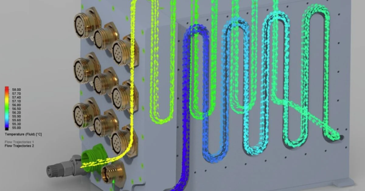
Our process begins at the system level, where we configure a chassis that properly integrates all your third-party plug-in cards. We then validate these designs using thermal simulation software and test equipment. This approach mitigates risk, accelerates development, and yields a design that precisely balances performance and reliability for MOSA and SOSA®-aligned platforms.
The success of an embedded computing system depends on a thermal design that can meet its mission profile. Let our technical experts help you find the right solution for your application.